Week 10 Meeting 2
In attendance: Jairo, Kai, Calvin, Luca, Jesse
- IDP wrap up meeting
- Worked on team deliverables
- Industry consultant summary
- Went back and updated all our weekly meeting details
- Worked on CAD designing the updated collar
- Deconstructed frame to add new inserts
Plans for next meeting:
- Print out new collar
Week 10 Meeting 1
In attendance: Jairo, Kai, Calvin, Luca, Jesse
- Made finishing touches to poster and turned it in
- Printed out collar and new rail inserts
- Collar does not fit around PVC
- Need to reprint and redo tolerances
Plans for next meeting:
- Print out new collar
- Fasten new brackets to the frame
Week 9 Meeting 2
In attendance: Jairo, Luca, Kai, Calvin, Jesse
- CDR presentation
- Dr. Hamel and Dr. Gilbertson had lots of good critiques for us to consider
- What is the purpose of the chamber?
- Too short
- Do we still need the chamber, or should we get rid of it entirely?
- How are we going to constrain the piston?
- Rail inserts on sides are not doing the job
- Should find a way to constrain the PVC near the end
- Discussed idea for a collar to constrain without adding too much friction
- “Need” a little bit of friction during stroke to achieve consistency
- Priority is generating enough power to make the 10-foot distance
- Can make changes after that
Plans for next meeting:
- Generate ideas for design solutions based on critiques we received during CDR
- Work on poster due on Monday
Week 9 Meeting 1
In attendance: Jairo, Luca, Kai, Calvin, Jesse
- Assembled new piston and chamber assembly
- New threaded inserts work well, but still have issues with non-linear launch stroke
- Friction still occurring due to the stroke not being consistent
- Worked on CDR slides
- Divided slides among group members
Plans for next meeting:
- Continue work on CDR, prepare slides and script for presentation on Friday
- Assemble current prototype to be showcase ready for CDR
Memorial Day
No Meeting (Memorial Day Holiday)
Week 8 Meeting 2
In attendance: Jairo, Luca, Kai, Jesse
- Ran initial launch tests late Wednesday night
- Need much more power than what our current bungee cords are generating
- Ideas for stronger bungees, longer launch stroke, etc.
- Trigger mechanism broke during initial testing
- Need to figure out a way to bolster the structural integrity of the trigger
- If no ideas arise, we may need to move away from our idea
- Reworked our piston design to minimize friction
- Using PVC pipe rather than a full 3D print piston
Plans for next meeting:
- Begin work on CDR
- CAD new piston design
- Print and assemble next week
Week 8 Meeting 1
In attendance: Jairo, Luca, Kai, Calvin, Jesse
- Started printing 45˚ brackets and trigger
- Gathered t slot nuts and bolts as fasteners to the frame
- Assembled chamber and piston with bungee cords
- Did preliminary pull tests
- Noticed lots of noise and friction occurring between the chamber and piston
- Need stretchier/longer bungees to generate more elastic energy
Plans for next meeting:
- Get chamber and piston attached to the base frame
- Run launch tests
- Work on design solutions based on what goes right and wrong during testing
Week 8 Meeting 0
In attendance: Jairo, Luca (not a dedicated project workday)
- Started printing out the brackets
- Discussed how to secure brackets to the frame
- Started working on outline for CDR
- Started printing new chamber and piston
Week 7 Meeting 2
In attendance: Jairo, Luca, Kai, Calvin, Jesse
- We got a good grade on the PDR yay!
- Moving away from a 3D printed base
- Making a frame out of aluminum extrusions
- Plan is to cut out extrusions and bracket them together to form the base
- Need to print out our own L brackets
- Discussed idea of putting a “skirt” or “wedge” along the edges of the base to help improve friction by digging into the carpet
- Talked with industry consultant (details on interaction summary)
- Decided to move away from the angle mount
- Plan is to simplify our design to minimize variables and reduce manufacturing time
Plans for next meeting:
- Cut out aluminum extrusions
- Figure out how to attach our launcher to the new base
- Print out L brackets and 45˚ brackets
Week 7 Meeting 1
In attendance: Jairo, Kai, Jesse, Luca
What we did
- Noticed that we encountered technical difficulties and time constraints with the print time for our prototype model
- Scaled down our prototype model by 20% to cut down on print time
- Discussed future plans for laser cutting a wedge to mount onto the launcher in order to maintain the launcher in place
- Discussed manufacturing the base of the launcher out of aluminum
Plans for next meeting
- Manufacture and assemble the prototype model by next week
- Begin launch tests
Week 6 Meeting 2
In attendance: Jairo, Kai, Jesse
What we did
- Jairo and Kai have finished their design for their respective parts
- Jesse is working on creating an arm and fixed pivot point for the launch mechanism
Plans for next meeting
- Compile each component into a SOLIDWORKS or Onshape assembly
- Have each component laser-cut or 3D printed by next meet
- Physically assemble each component
- Run launch tests
Week 6 Meeting 1
In attendance: Jairo, Kai, Calvin, Luca
What we did
- Met in the CAD lab to start designing parts for the trigger mechanism, chassis, and implement some features onto the launch mechanism
- Jairo and Calvin are working on the rotary arm of the chassis so that the launch mechanism can be set to a certain angle
- Luca is tinkering with the launch mechanism
- Kai is working on the base of the chassis
Plans for next meeting
- Finish CAD designs start 3D printing components
Week 5 Meeting 3
In attendance: Jairo, Kai, Calvin, Luca
What we did
- Jairo presented a simple trigger design inspired by trigger mechanisms found in crossbows
- Luca presented a trigger and spring mechanism that is being pushed into a notch in our piston
- Kai presented an idea on how to mitigate the snagging of the piston on the chamber
- Calvin proposed a design for controlling launch angles inspired by lifting machines in the gym
Plans for next meeting
- Start to CAD out more fleshed-out designs for the chassis and trigger mechanism
- Implement notches in the piston of the launch mechanism, as well as connection points so we can attach the launch mechanism to the chassis
- Propose sub-teams to work on different components of the prototype
Week 5 Meeting 2
In attendance: Jairo, Kai, Calvin, Jesse, Luca
What we did
- Met briefly as a group to go over the final revision and the general plan for the presentation
- Presented our PDR
- Dr. Hamel and Dr. Gilbertson showed general praise of the presentation
- Dr. Hamel had concerns about our piston snagging onto our chamber wall
- Both noted our progress-saving mechanism and its complexity, and advised us to simplify the design
- Dr. Hamel also stated that he would’ve liked us to back our design up with a math or physics model
Plans for next meeting
- Jairo is to create a projectile motion model to help the team choose a launch angle and force required to launch the beanbag
- Each member is to create a simplified trigger mechanism and present it to the group, CAD is recommended
Week 5 Meeting 1
In attendance: Jairo, Kai, Calvin, Jesse, Luca
What we did
- Went over a couple of changes to the slides that happened over the weekend
- Did a group practice that went through the whole presentation, ensuring that we stayed within the 10-minute time constraint
- Calvin presented the proof of concept that we are to show Dr. Hamel and Dr. Gilbertson
Plans for next meeting
- Next meeting is the PDR presentation!
- Practice slides on your own
- Jairo will do the final revision of the presentation
Week 4 Meeting 2
In attendance: Jairo, Kai, Calvin, Jesse, Luca
What we did
- Calvin and Luca went down to the machine shop to 3D-print our proof-of-concept
- Jairo, Kai, and Jesse worked on the PDR presentation slides
- 3D printing started successfully, and will finish by the start of the evening
- Slides are almost completed, must touch up on pictures and diagrams
- Planned to work on slides asynchronously over the weekend
Plans for next meeting
- Do a final pass-through of the entire presentation
- Set time to practice on individual slides, as well as for group practice
Week 4 Meeting 1
.jpg)
In attendance: Jairo, Kai, Calvin, Jesse
What we did
- Calvin presented a proof-of-concept design based on our brainstorming ideas
- Initial thoughts were shared, and a discussion was held about the crank system
- Different designs of latches and triggers were brought up for possible reiterations of how we initiate the launch mechanism
- Von Mises stress analysis was done on the bungee cord attachments by Luca
Plans for next meeting
- Print the proof-of-concept for PDR
- Work on PDR presentation slides
Stress Analysis
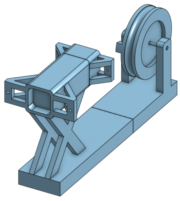
CHAMBER DESIGN IDEOLOGY
With a railgun / slingshot design, we were wondering how we could best design the part that would sustain the force of the bungee cord (or other energy conservation system) to launch the beanbag.
We need to create a design that optimizes:
- Tensile strength (Won't snap while applying force)
- Longevity (Can be repeated over and over without permanent deformation)
- Amount of materials used (More material may equal more strength, but is not practical for the machine)
For a first prototype, we are 3D printing our chamber and piston. This may change down the line as the layer lines of 3D printing may be a problem. We will try to print as much of it as possible with layer lines perpendicular to our force direction.
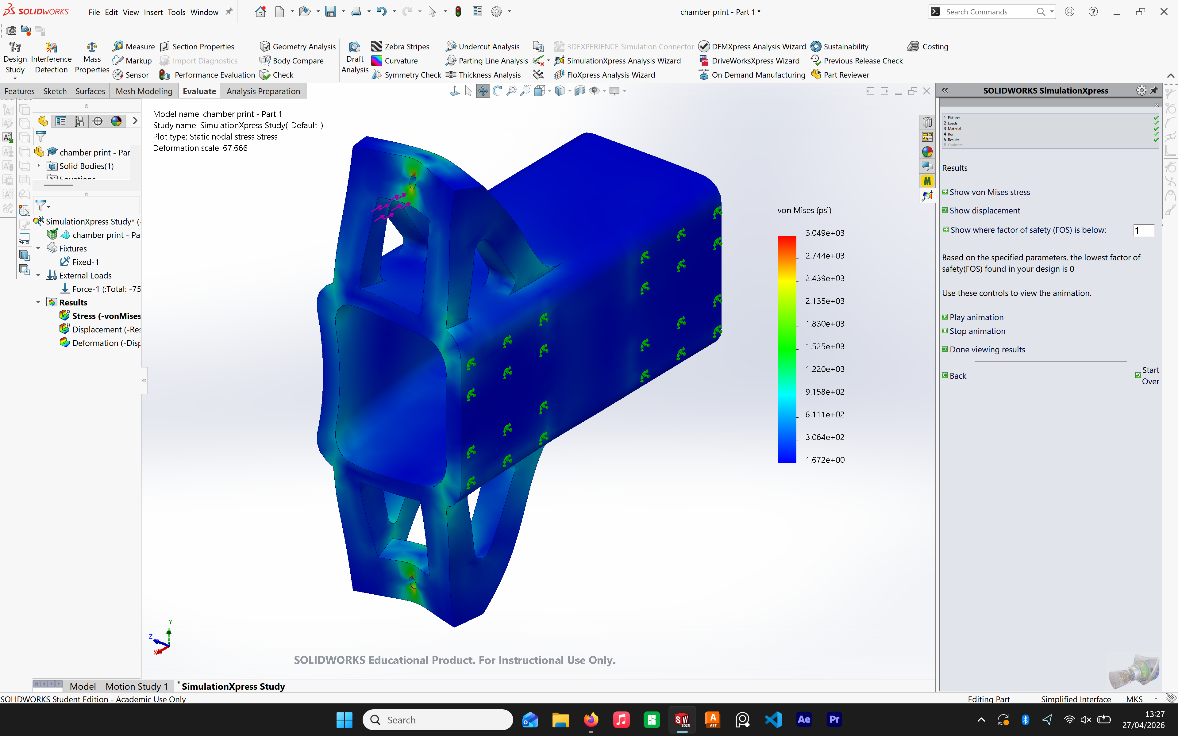
As an aid to our CAD development, we are running Von Mises stress analyses in Solidworks to identify crucial design changes (adding 45deg trusses, fillets) to help reduce concentrated stress and improve our design goals.
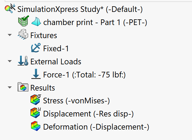
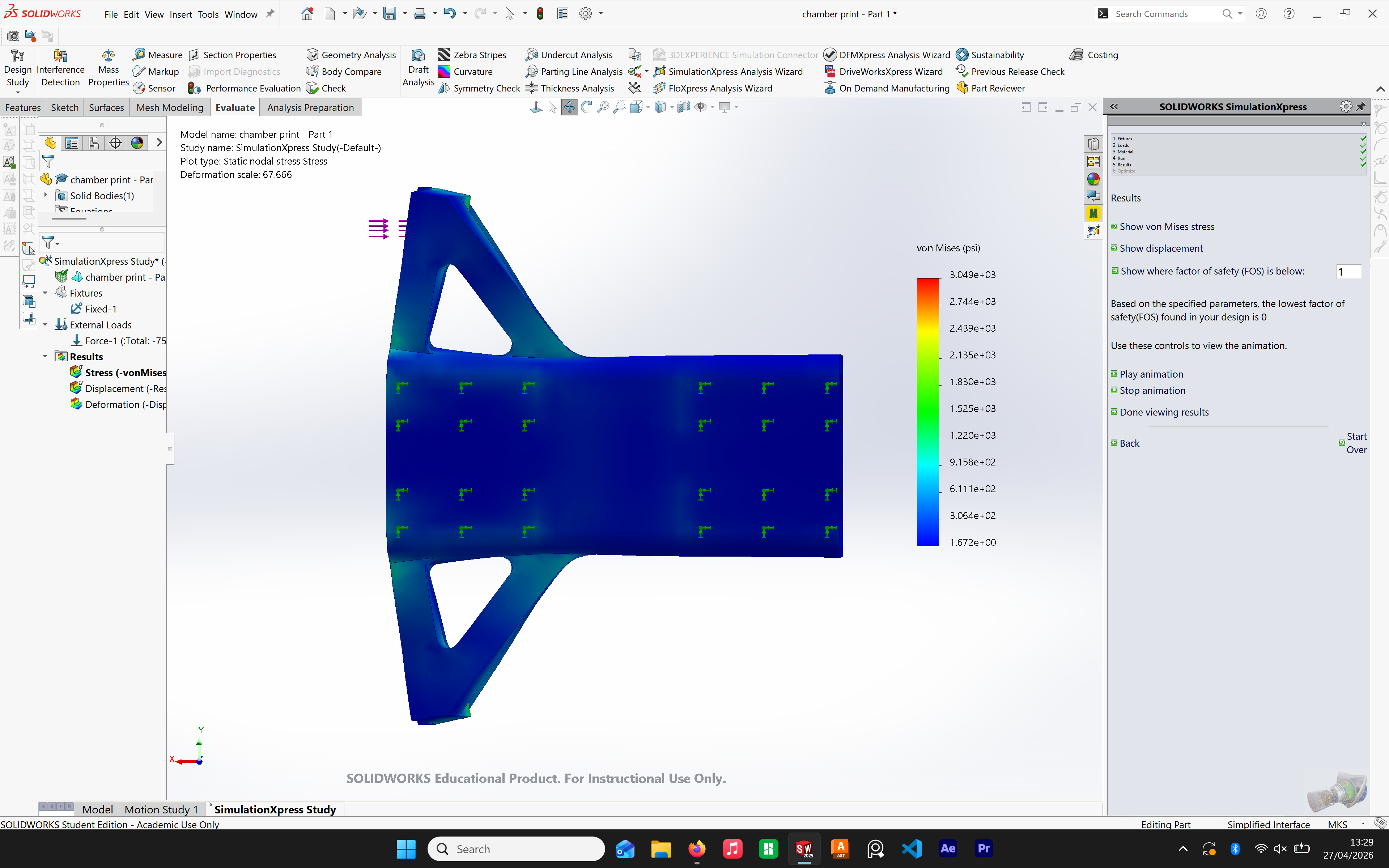
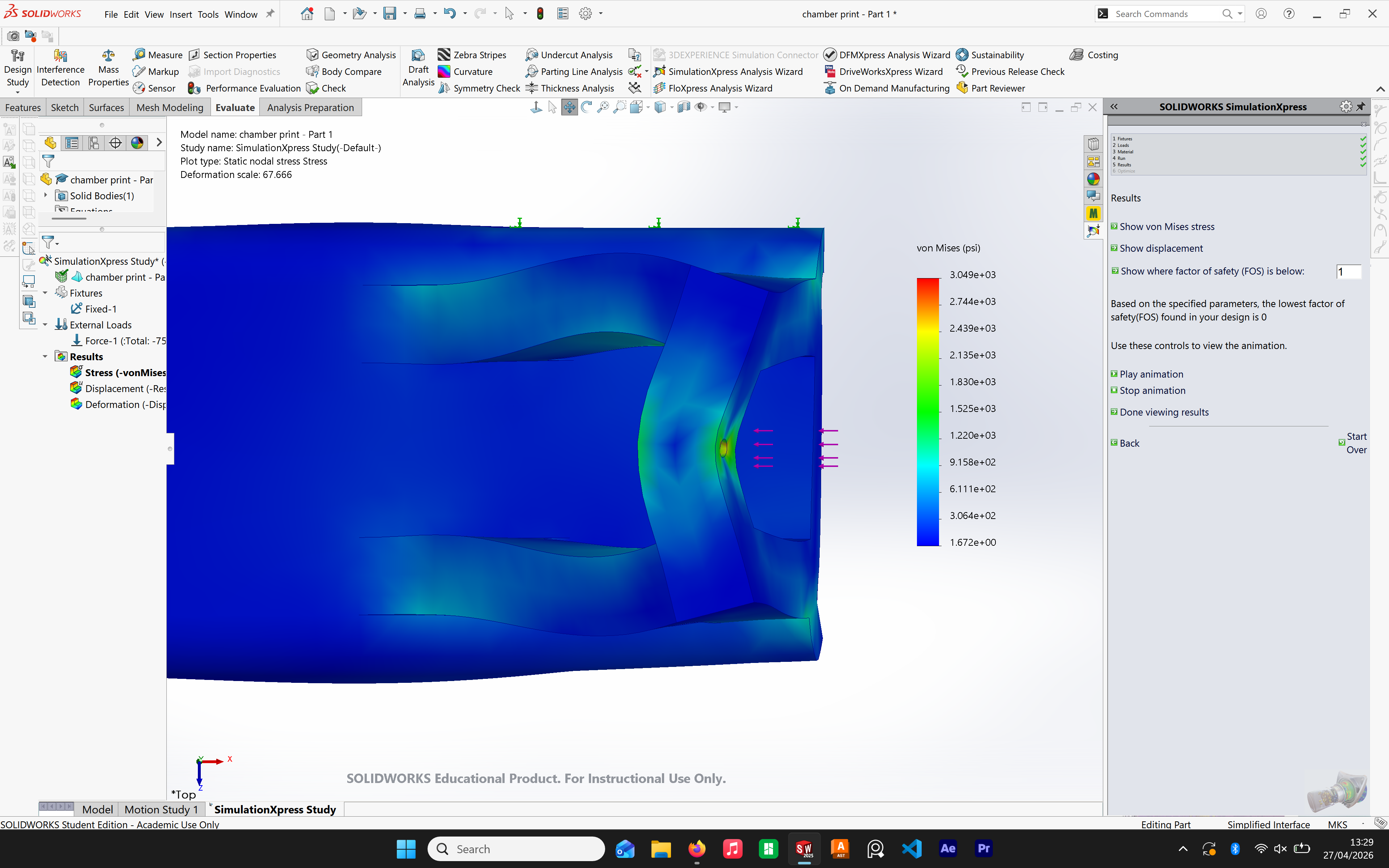
STRESS ANALYSIS + DISPLACEMENT ANALYSIS
Orange arrows represent contact area of machine base, pink represent tension force normal direction
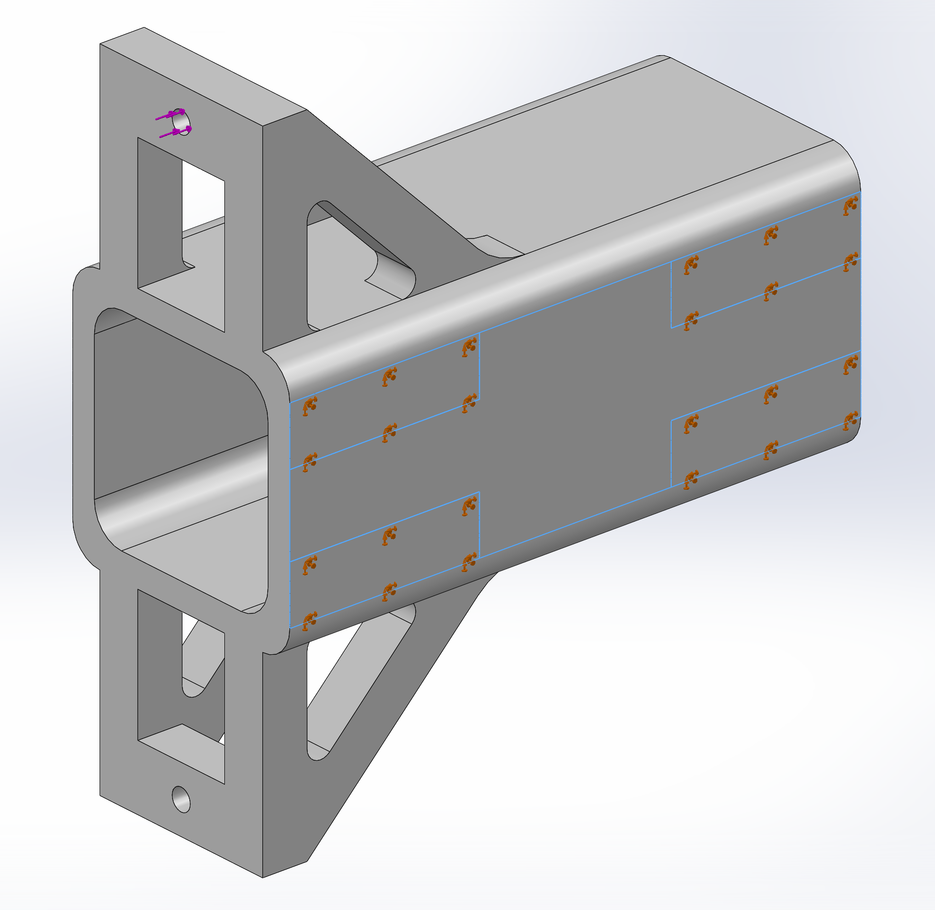
As a test, we are applying 75 lbf of force to each hole directly backwards. The simulation material is PET. Although reality is grossly different to our simulation because it doesn't account for any FDM layer lines, it is still helpful in the design process.
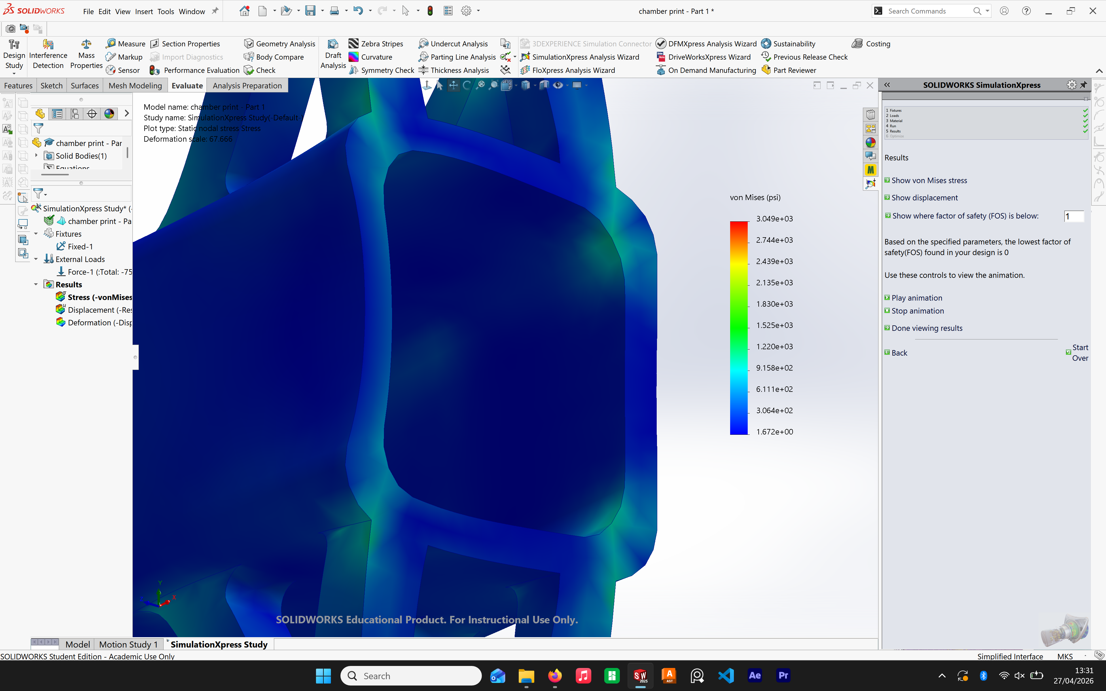
VON MISES STRESS
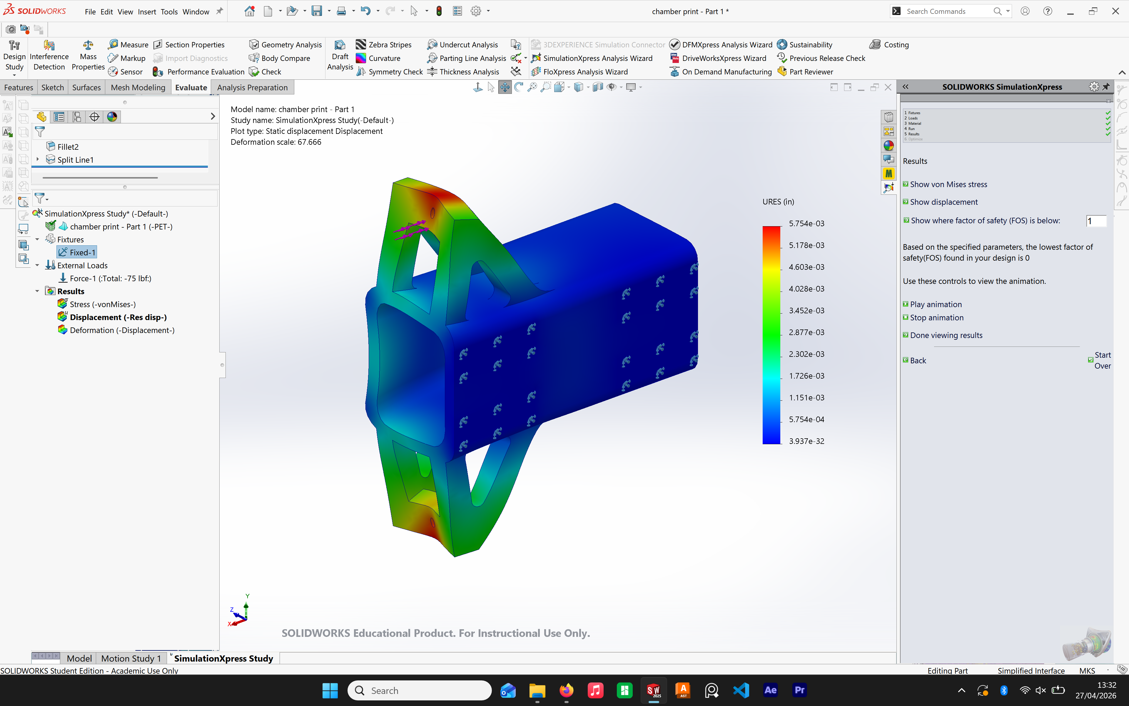
OVERALL DISPLACEMENT
FINDINGS SO FAR
From the stress analyses, our 45deg trusses did an excellent job of reducing stress at the intersection of the initial truss and the chamber. However since the truss thickness is nominal, we notice a strong outwards bowing on all the trusses, along with the chamber deflecting inwards some. Will this be an issue? Will the bean bag get stuck? Not sure, we will keep exploring.
From the displacement analysis, it's pretty clear we should distribute the load more evenly on the surface rather than just on the hole. Although it will be a bit more distributed if we were to tie a knot around the hole, we can come up with another way.
Week 3 Meeting 2
.jpg)
In attendance: Jairo, Kai, Calvin, Jesse
What we did
- Fleshed out our brainstorming ideas more
- A vote began on which idea the team was to adopt
- Listed pros and cons, noting feasibility and budget, and other concerns for each idea
- Will move forward with Jairo’s slingshot railgun idea
- Calvin added that we can add a hook and pulley system to pull back the pouch
- Calvin and Kai also noted that grips can be added to the chassis to minimize slipping
- Met with Industry Consultants Steve Brooks and Brian Nasralla
- Steve’s points:
- Know your team and how to communicate (even the hard talking points)
- Many ways to get involved other than internships:
- Volunteer
- Clubs
- Personal projects
- On-campus resources
- Brian’s points:
- Brian brought up a few general points on what aspects are important for our project:
- Repeatability is an important factor for this design problem
- Minimize vibrations and small movements of the chassis
- Must ensure that the chassis position will remain unchanged to ensure that the shot won’t deviate
- Know what material the mechanism will rest on to account for any movement due to the lack of friction
Plans for next meeting
- Create proof of concept for PDR
- Start working on the PDR presentation
Week 3 Meeting 1
.jpg)
In attendance: Jairo, Calvin, Kai, Luca
What we did
- Brief recap and reintroduction
- Each member presented their own initial ideas
- Catapult system introduced by Calvin and Kai
- Luca presented a flywheel concept
- Jairo introduced a slingshot system
- Ended with quick recap and refining ideas
Plans for next meeting
- Narrow ideas down to a handful
- Hold a vote for which idea the team will move forward with
Week 2
What we did
- Introductions and getting to know the team
- Team Charter formed
- Form of communication established
- PDS sheet completed
- Website published and running
- Beginning brainstorming
Plans for next meeting
- Each team member to present ideas for the problem statement
- Emphasis on ambitious and varied ideas (focus on the ‘what’ not the ‘how’)
Go Back